Analysis

Project F1/10th consists of many different parts. For the truck to meet the team's requirements, analysis was done on parts to confirm their design. A combination of mechanics of materials, physics, geometry, dynamics, statics, and mechanics of materials is used in these analyses. These analyses were used in the design and creation of the truck.

Requirements
-
The suspension will complete a “drop test”, a standing fall from 600mm without the suspension of the vehicle “bottoming” out. Bottoming out will be defined as the moment when the spring component of the vehicle can no longer compress.
-
The suspension must have remaining room to compress when completing this test.
-
The vehicle must sustain no damage when completing this test.
-
-
The Steering will complete a full 180-degree turn within a 1200mm diameter. The vehicle will maintain a 600mm turn radius.
-
Suspension and steering components will return to the wheel side of the car on at least 3 separate drops in the event of a 300mm drop with the vehicle pitched at a 45-degree angle from horizontal.
-
Steering arms will be adjustable up to 7mm which will be utilized in the alignment of the tow of the vehicle.
-
Sprung suspension components will be able to support 25N of tension, including limiting straps and bump stops if installed.
-
The suspension will have less than 10 degrees from the centerline of “bump steer”. In other words, as the shock travels, the toe of the vehicle will change less than 10 degrees.
-
The vehicle will maintain at least 75mm of ground clearance stationary.
-
The Suspension components will experience less than 10mm of additional “droop” from the addition of wheels while held in the air.
-
The rear suspension will never differ more than 30 degrees from the chassis by utilizing a rear sway bar.
-
The front suspension, when viewed from a side profile will be contained within a 125mm square window and maintain a 300mm trackwidth. This trackwidth constraint will also apply to the rear wheels.
Drop test
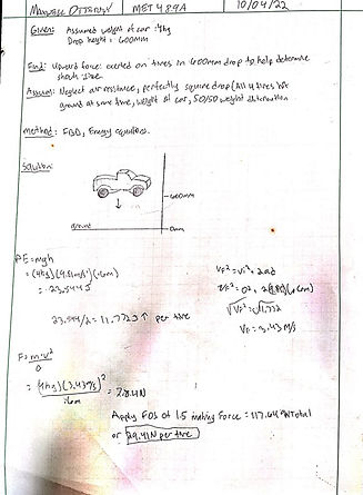
For analysis A-1, The impact force that will be used in the 600mm drop test will be used (Section 1d.1). This calculation shows the maximum upward force exerted on the suspension when the truck undergoes this test. The potential energy equation PE=mgh was used to find drop energy, the kinematic equation Vfinal^2=Vinitial^2+(2)(acceleration)(distance) was used to find velocity, and the impact force equation f=mv^2/d was used to find the final force, see appendix A01 for analysis. The suspension components can be designed with this force in mind. A safety factor of 1.5 was added to the analysis to prevent failure. The total force found was also divided by four as the truck is assumed to have a near 50/50 weight distribution and dropped parallel to the ground. The result of this analysis yielded a force number that will be used to determine how much force is expected to travel through the suspension components.
Image A1

Steering angle and sub frame width
For analysis A-2, A turn radius analysis was done to determine the angle of steering needed to comply with this requirement. The full sheet can be found in appendix A02. The equation TR=WB/tan(a) was used to determine the angle required off zero degrees being straight to complete the turn in the specified 600mm radius. This number was computed to be 28.44 degrees. This is the minimum angle required to make this turn. Max decided to change this value to 35 degrees to enable even more angle. With this information, trig was used to find how far the edge of the tire turned in when at full 35-degree lock. This was found to be about 225. The result of this analysis was to determine the maximum width of the frame rails and front subframe so the tires will never hit at full turn. This information is crucial in the design of the front subframe as it provides a building block of the front suspension.
Image A2

I-beam geometry
For analysis A-1, The dimensions and geometry of the front I beam suspension was designed (full sheet found in appendix A03). A requirement 1d7 stated the truck needs to have a 75mm ground clearance. The sub frame and wheel spindle were placed in proper locations to achieve a 75mm ground clearance and the I-beams were designed off that. The geometry and sizing were determined using trigonometric equations. The front sub frame was used as a reference for mounting location on the frame. These calculations were essential in the design of the I beam due to its complex geometry.
Image A3

Rear trailing arm
For analysis 10, the minimum cross-sectional area as well as shock location was found for the rear trailing arm (appendix A-10). The axel and frame were positioned where they needed to be to fit within the wheel well of the chosen body. This enabled the geometry of the rear trailing arms to be found. Once found the shock travel and trigonometry was used to determine where along the arm the shock needed to be placed to utilize full travel. This was found to be 72.43mm from the frame mount. One proper shock location was found the drop test date (requirement 1d1) was referenced to find the forces applied to the trailing arm using moment equations. Once the forces were found, the max shear equation was used to find the minimum cross-sectional area of .25mm squared.